Hardwiring, Layout Problems | Solutions To These Problems |
Power Supplies and Capacitors | Interstage Signal Feedback Through the Power Supply | Resistor comparisons
Home Page | Reviews |
Tube Preamplifiers | Tube Amplifiers |
DIY Parts/Price list | Warranty |
Specials | Contact, Directions | Audio Links | NEW: Forum
In almost every multi-stage component designed, using a common power supply, and built that I have seen, there exists an insidious form of musical feedback that is frequency dependent, and with varying degrees of phase shifting. RCA Radiotron Designers Handbook, 4th edition, saw this problem in the 40s, but I am sure it was apparent much earlier. With different signals and different phases of feedback one can see it being a serious distortion problem unless the proper precautions are taken?
How serious is the problem? Serious enough that an oscilloscope can easily measure it despite using the typical "decoupling capacitor(s)", and using sophicated listening tests. It is at least equivalent to changing resistor and capacitor brands, which are known to cause sonic changes. Remember that even if the problem is -60db down signal voltage wise, power wise it is only -30db.
Let's analyze some examples.
First, let's check out a simple circuit (fig. 5) and see what we can discern. (We will only address tube circuits although solid state designs are similar.)
Fig. 5 is a typical capactively coupled tube stage. From our previous article ,"Power Supplies and Capacitors"), C1 should theoritically be 0 ohms impedance at all frequencies. However, in practice this isn't true as no capacitor is infinitely large, and all have ESR and DA problems anyway.
The equation for capactive reactance is Xc = 1 / 2pi FC, where:
Xc = capacitve reactance
pi = 3.1416. 2pi = approx 6.28
F = frequency in hz
C = capacitance in farads. For example, 1uf = 1 times 10 to the minus 6 farads, or 1x 10 -6.
As an example, the capacitive reactance of 10uf at 20hz is calculated: 1 divided by 6.28 times 20 hz times 10x 10 -6. This calculates to approximately 796 ohms impedance. At 200hz the 10uf capacitor still has approx 79.6 ohms impedance, and at 2khz approximately 7.96 ohms impedance, and at 20khz approximately .796 ohms impedance. By the way we are not counting internal capacitor inductance at higher frequencies.
IMPORTANT: As one can see decoupling capacitors do not completely eliminate the musical signal, even at very high frequencies. And phase problems occur not only at 20hz, but even at 200hz and higher.
As a general rule, the signal voltage present at capacitor C1 is dependent on:
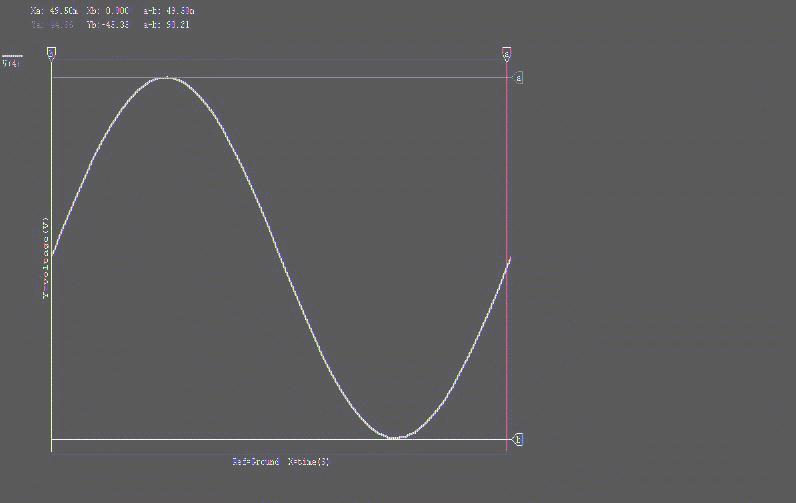
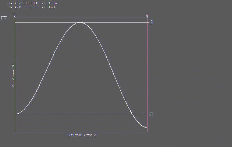
Capacitance of C1          Frequency           Voltage P-P at C1       Phase Shifts

10uf			      20                     4.5 volts      Lagging nearly 90 degrees
20uf                          20                     2.3                      "
40uf		              20                     1.15	              "
100uf                         20                      .465		      "
Even with C1 at 100uf and R1 of 15k, some .465 volts appears at C1 at 20hz, which is only approximately 46db down from the 90 volts present on the plate of V1. As mentioned above, the resistance of R1 also determines the signal voltage present at C1 as follows:
Resistance of R1         Voltage P-P at C1

15K			        2.3
150k		               .24
Typical 20hz signals at C1 (I have seen in some tube designs) range from only -21 to --45db range below the reference at the plate of tube V1, which is very poor. Increasing the frequency an octave accounts for only an approximate 6db reduction of this signal at C1 (while the ear becomes more sensitive). As we shall see in a moment, this will interact with the previous stages.
Let's look at some typical 2 stage designs in fig. 6 and fig. 7:
Fig. 6 adds another gain stage, and is typical in many designs I have seen. Feedback is occurring between V2 and V1, thru R1 and R3s, with C1 the imperfect signal grounding decoupling capacitor. In otherwards, low frequency signals (with large phase shifts) from both tubes are mixing, and is easily measurable at C1. From there, each tube's signal reaches the other's tube plate via the RL of that tube.
If we have 90 volt signal on the plate of V2, we know the signal of C1 (with 40uf capacitor) is 1.15 volts. Let's make the plate resistance (Rp) of both V1 and V2 a low 3k ohms. The signal feedback voltage reaching the plate of V1 is approx 0.1916 volts. Let's say the gain of V2 is 10 times or 20db gain. That means we have 9 volts on the plate of V1. So the feedback voltage, 0.1916 volts, is approx 33db down from the fundamental, 9 volts. Visa Versa, the low frequency voltage from V1 to V2 is approx 73db down. So "feedback" occurs both ways.
On a side note, if we make C1 a typical electrolytic capacitor and continue to increase its uf size, the feedback will lessen as the frequency increases, until the capacitor reaches its resonance, which may be as low as 5khz. Above the resonant frequency, the capacitor becomes more and more inductive and its reactance again rises, thus again increasing the feedback, but this time at high frequencies.
Fig. 7 adds an RC combination to the power supply circuit and adds, typically, another 10-30db of isolation, so maybe between 45-75db of signal voltage isolation total. However, power wise we are only between 22.5 and 38db down. We also increase the phase shift of the feedback signal to a possible 180 degrees.
Replacing R4 with an inductor can actually worsen the feedback condition at low frequencies. This is because the reactance is low at low frequencies, often lower than using a resistor. It also changes the phase shift pattern and also creates a resonant circuit at some X frequency.
What if in Fig. 6 and/or Fig. 7, V2 is an output tube with R3 replaced by a typical audio output transformer. The interaction between V2 and V1 will be tremendous as the signal voltage of the output tube may be typically 250 to 500 hundred volts p-p, and already with phase shifting in the bass region. In multiple stage amps using these types of power supplies, we will see feedback to every previous stage of the amp, unless some extraordinary precautions are taken..
I hope you see how much of a problem the power supply can be. It not only supplies pure DC voltages to each stage, but also should eliminate incoming interference, and eliminate "hidden" frequency dependent feedback between stages.
This article was meant for the general audience, in simple language.